The Rig.
Materials, design, physics.
The rig is a model-scale autonomous drilling system — a vertical aluminum tower built to drill into an unknown rock block, then steer the bit through three target points with no human intervention.
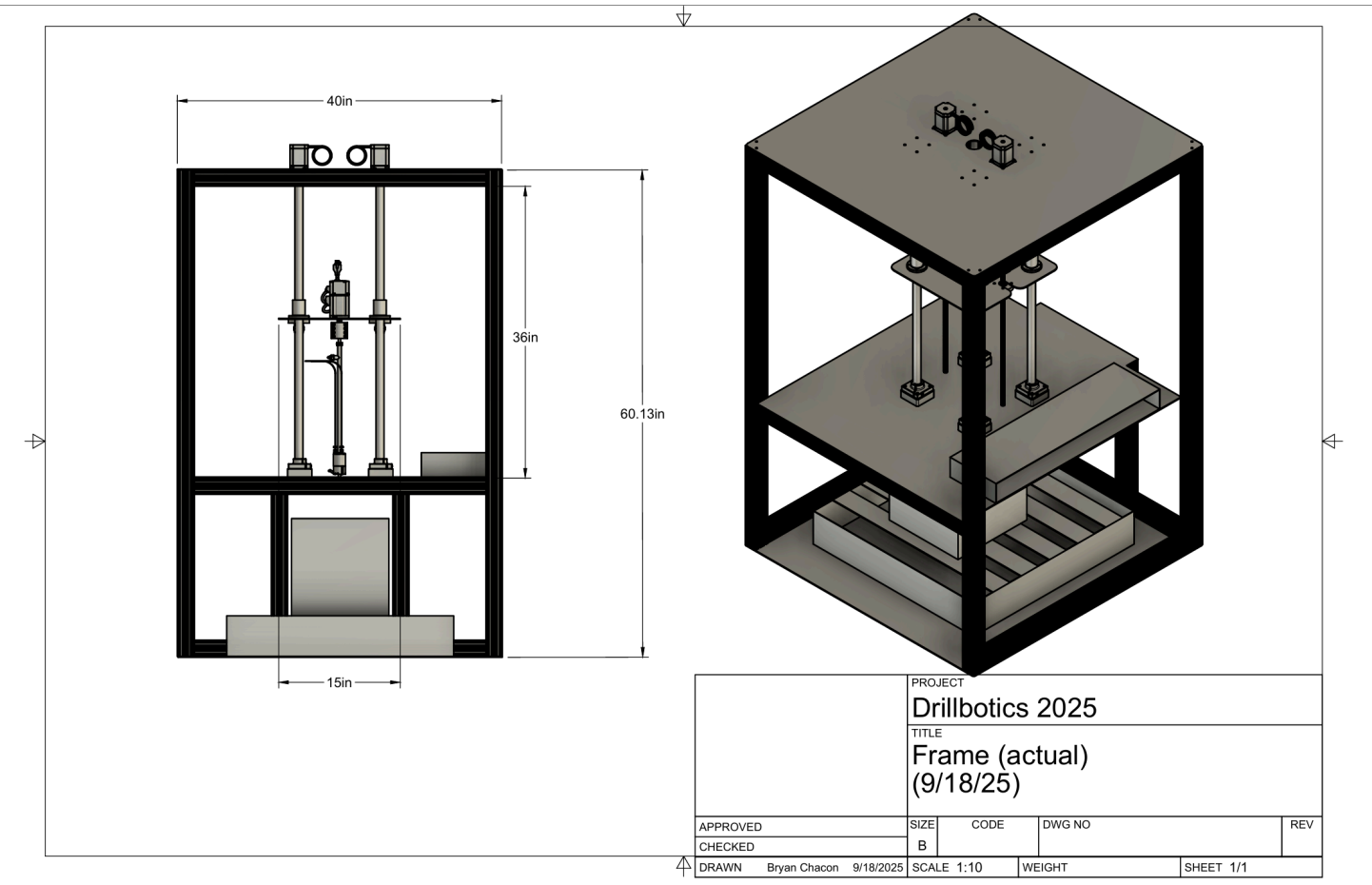
The frame is a modular tower of 6061-T6 aluminum 2-by-2-inch T-slot extrusion, joined with aluminum corner brackets and thread-locked fasteners. The modular T-slot profile allows for customizable sensor mounting and reconfiguration. Three platforms carry the subsystems — a top actuation deck, a mid-frame elevator carrying the drillstring and top-drive assembly, and a bottom platform for fluid and cutting collection.
Vertical motion comes from two NEMA-32 stepper motors driving lead screws; sharing the load gives a lift capacity near 700 lb and sets weight-on-bit through the elevator platform.
Steering uses a hydraulically actuated push-the-bit rotary steerable system — three independently controlled wings, each driven by a dedicated piston near 2000 psi, biasing the bit toward the commanded direction. Safety is built into the structure: a polycarbonate enclosure contains debris, door interlocks gate operation, a hardware-and-software E-stop cuts power, and the hydraulic seals are sized to fail before any structural component does.
- Material6061-T6 AL
- Extrusion2 × 2 IN T-SLOT
- Platforms3-TIER
- Lift Capacity≈ 700 LB
- Total Height≈ 60 IN
- Steering3-WING RSS
- Drive Shaft17-7 PH SS
- Drill PipeFLEXIBLE NYLON
- Hyd. Pressure≈ 2000 PSI
- Bit1.75" PDC

Three wings, one trajectory.
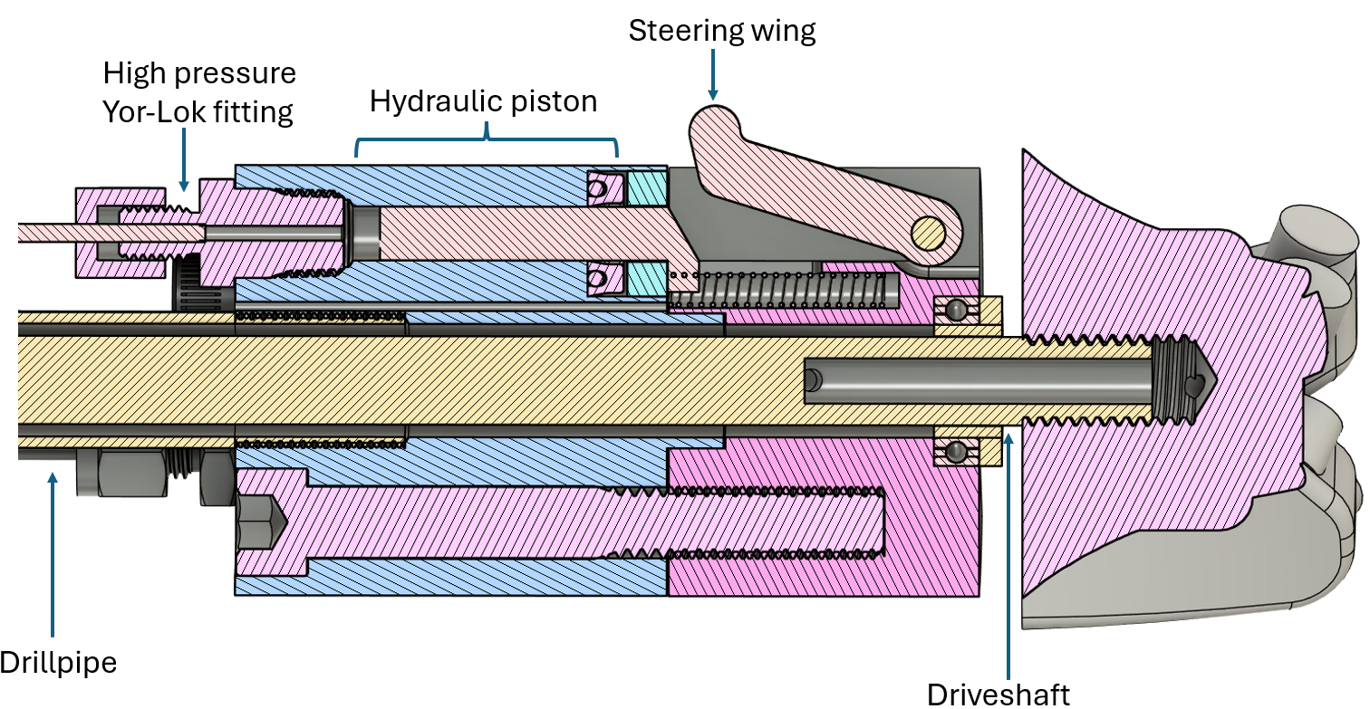
Steering. Once the bit enters the rock, a rotary steerable system bends the well toward three target points — no tripping the string, no human intervention.
The RSS is a push-the-bit design: three steering wings spaced evenly around the bottom-hole assembly, each driven by its own hydraulic piston. A wedge mechanism converts piston extension into radial wing deployment, forcing the wing against the wellbore wall — and the reaction force biases the bit toward the commanded direction.
Each wing is controlled independently through a hydraulic block that monitors flow and pressure. Those readings estimate actuation force and wing extension, which in turn resolve the bit's toolface and orientation relative to the formation. Fully retracted, the wing tips sit slightly proud of the BHA to double as drilling stabilizers.
High-pressure hydraulics demand a deliberate failure mode. Yor-Lok fittings and stainless tubing carry margin to roughly 9000 psi against a ~2000 psi working pressure, while the U-Cup piston seals are sized as a mechanical fuse — the weakest pressure boundary, designed to fail before any machined steel component does.
Code that controls.
A real-time control loop closes around every revolution of the bit — embedded C on an STM32 microcontroller, deterministic to the microsecond.
The firmware layer runs priority-pinned tasks for sensor acquisition, control compute, and CAN dispatch. PID controllers regulate the coupled drilling axes (RPM, feed rate, and weight-on-bit) and drive the steering response that holds the bit on its commanded trajectory.
An ML interfacing layer pipes a downsampled sensor frame over high-speed serial to a co-processor running inference, then receives gain-trim and setpoint deltas back. Control authority always sits with the deterministic PID core, with the ML layer recommending.
Telemetry is broadcast over CAN to a Raspberry Pi 4 that handles logging, the operator UI, and diagnostics — capturing every run at 1 kHz for offline analysis and model training.
Sensor fusion meets machine learning.
Unified state from messy reality.
A Kalman-style estimator combines pressure, torque, RPM, depth, and IMU streams into a single bit-state vector — denoised, time-aligned, and physically-constrained. The fused estimate is what the controller and ML layer see.
Offline, dataset-driven, reproducible.
Recorded drill runs form a versioned dataset; models are trained in PyTorch with deterministic seeds and checkpointed to a registry. Each release ships with a model card, hyperparameter manifest, and evaluation harness.
On-rig, low-latency, advisory.
Quantized models run on a dedicated CUDA-accelerated edge module beside the controller. The inference pipeline is hard-budgeted: drop a frame, miss a deadline, fall through to PID-only.